Anodizing Plant Division
APC – Anodizing Process Computer
How to control all anodizing parameters
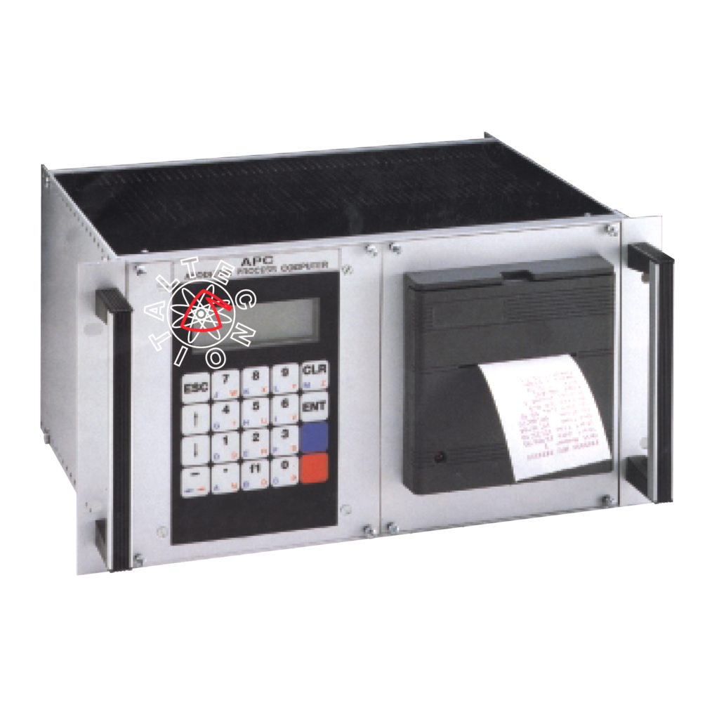
- Automatic survey of the surface to be anodized
- Presetting of anodizing current density
- Presetting of the requested number of microns
- Automatic printout of anodizing parameters
CONNECTIONS
This device, inside the control panel of the rectifiers, is already connected to the rectifier. The user only has to connect the temperature probe to the terminals 8-9-10 (9 and 10 for the same colour) prior to startup of the rectifiers.
KEYBOARD
The programmer is equipped with alphanumerical keyboard which enables the input and the modification data.
Besides the normal digital keys there are different special keys too, escribed below.
Key “CLR”: to clear the screen and correct wrong data entry and to quit any menu.
Key “ENT”: it confirms the working you are carrying out. In case you are entering data, it carries out data storage.
Key “ESC”: it stops any working you are carrying out, and resets the previous mask.
Key Arrow Top and Arrow Down scroll keys.
MAIN MENU
(Accessible only when the rectifier is not working)
Items that can be programmed freely:
TIME – DATE – LANGUAGE – UNIT NUMBER
Items that can be programmed by means of key switch set on “Programming”
CALIBRATION
MICRON CONNECTION
WORKING TEMPERATURE
INITIAL CALIBRATION
- Switch on “Programming”
- Enter the main menu
- Working temperature
If it is different from 18°C (factory calibration value) you must type in the new data. Press ENT
CALIBRATION
Calibration on a small load (it corresponds to 10%-20% of rated current of rectifier) of known surface.
Type in the m2 data and the number of requested microns.
Carry out the anodizing treatment.
At the end of the work press ENT. Calibration on big load (50% + 70% of max current) of known surface.
Type in the m2 data and the number of requested microns.
At the end of the work press ENT.
At this moment the device is automatically calibrated in the full range small up to big loads.
Micron corrections (if necessary)
- “programming working” switch set on “working”
- Enter the required density value
- Enter the number of requested microns
- Enter the start button
- At the end of the treatment check the number of microns actually obtained and compare it with the programmed one
If the difference is more than one micron, operate as follows
- Switch on Programming
- Enter the item “micron correction”
- Enter the number of microns obtained
- Enter the number of microns programmed
- Press ENT
- At this moment the device corrects itself automatically
THE USE
After the initial proper calibration (as above explained) the operator must enter the following parameters only:
- Requested number of microns (1/40 microns)
- Current density value (A/dm2) (0.50 A/dm2 / 9A/dm2)
(These values remain automatically memorized for subsequent treatments)
When the present number of microns has been reached, an acoustic visual signal is given and the output current of the rectifier decreases automatically and gradually up to 10% approx. of the working value till the stop button is pressed.
PRINT SWITCH
If it is on pos. “Yes”, at the end of the treatment you have automatically the print out of:
Data – start time – end time – duration – surface (SQM) – microns obtained – microns preset – vol – ampere – temperature
Parameters shown on the display during working: microns surface (sqm) time elapsed, temperature, growing up microns
REMARK
In order to carry out correctly the survey of the surface to be anodized it is absolutely necessary that electrical connections between rectifiers and tank are made soas to avoid anomalous voltage drops (defective connections, imperfect mobile contacts).
Feel free to ask to our commercial department
service@italtecno.com